METALLURGY
JOEST Special Charging Feeder
"JOEST is known globally as one of the world’s largest manufacturers of vibratory equipment for the foundry and other industries."
After introducing Joest’s equipment to the North American market in 2006, Joest has quickly gained the reputation for robust equipment and unique approaches to solving industry challenges with custom designs. Some of these designs lead to 10’s and 100’s of sales as standard equipment. Others do not gain as wide a distribution because they are manufactured to such specific, isolated requirements to match a particular customer’s process.
For foundry melt shops the challenges start at the beginning with charging cars. Generally used to provide scrap, virgin ore and alloys to the charge furnace, they must be designed around each customer’s particular type of materials, furnace interface and processes. There is also the need for the charge car to be mobile so it can be positioned over the furnace when charging and also moved away from the furnace for loading, maintenance and durability.
REQUIREMENT
- Store and feed raw material into the furnace at a rate that optimizes productivity.
- Movable for maintenance, access and durability.
- Withstand high temperature – Mechanically and electrically.
- Nose piece made of heat resistant materials due to extensive time directly over the furnace.
- Feed alloys as well as raw materials.
- Ability to control the sequence and flow rates of different materials into the furnace to achieve specific charging recipes.
- Feedback loop to communicate completion of cycle and amounts actually dispensed.
- Automatic operation to reduce personnel costs, and increase accuracy and repeatability.
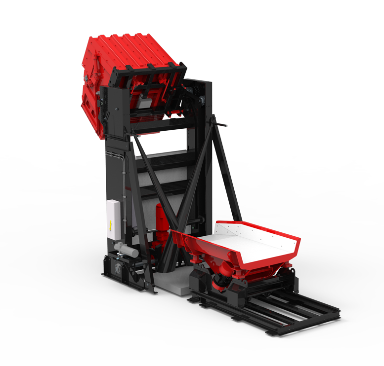
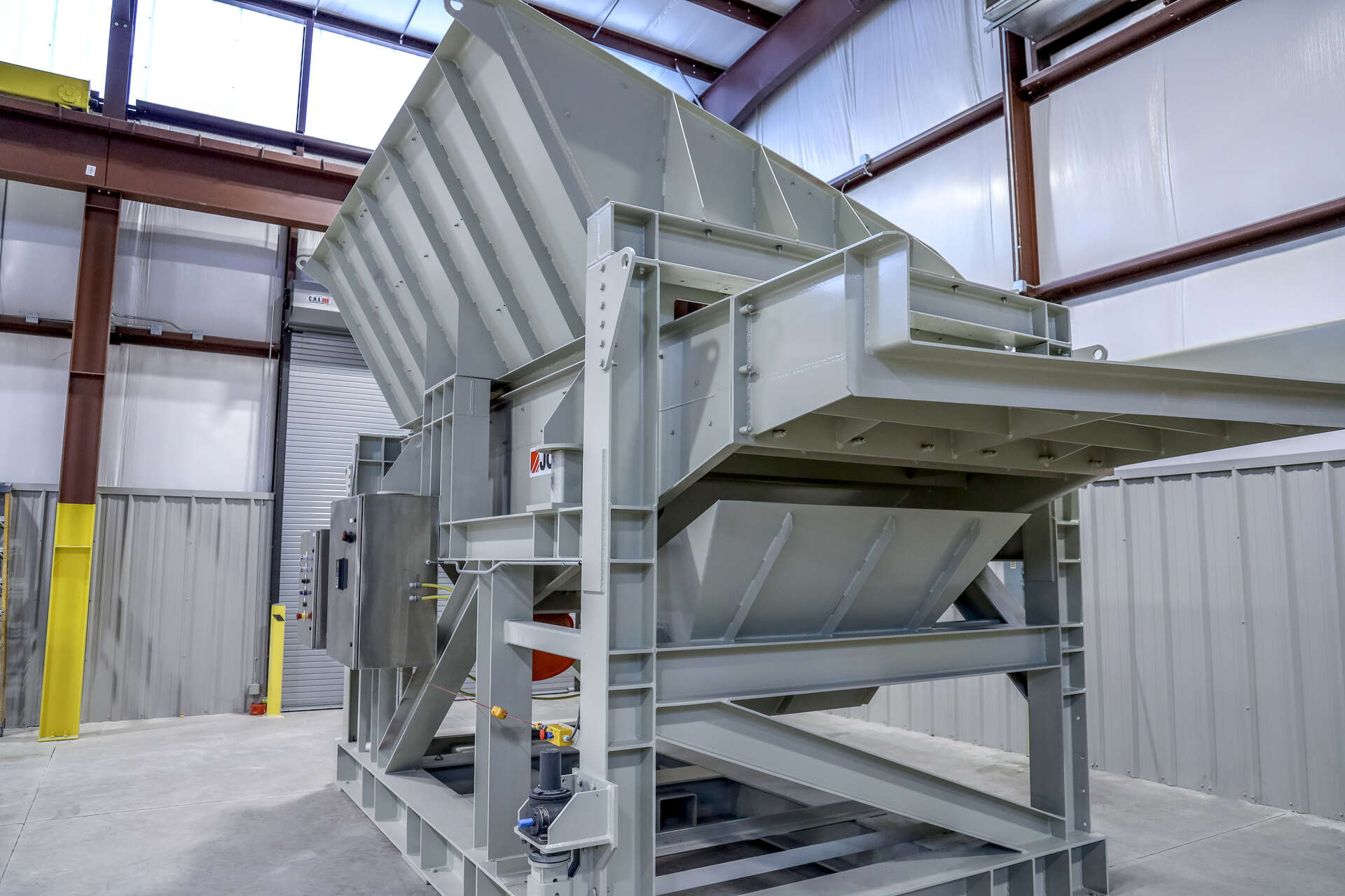
One of the world’s largest aluminum die casters came to Joest for a solution to charge their furnace more efficiently and reduce the risk to bucket loader operators from charged air bag ignitors and other devices exploding when they are fed into the furnace. The major hurdles included (1) The system had to be able to screen out fines while still being able to feed alloying materials, (2) The heavy feeder needed to be moved manually and safely back and forth from the furnace for maintenance over a rough, relatively unfinished floor, and (3) The method used to secure the feeder in place next to the furnace had to be simple, low cost and reliable.
![]()
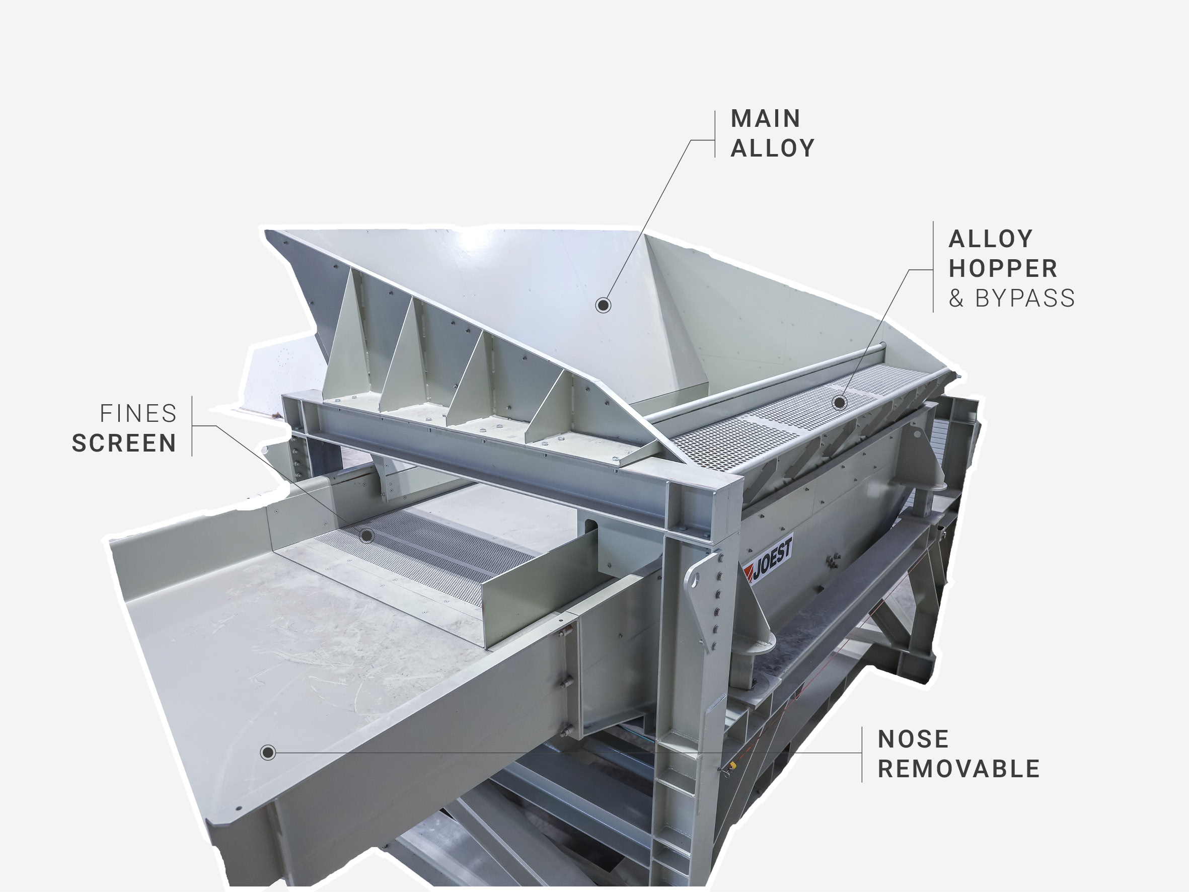
REMOVAL OF FINES CONTAMINATION
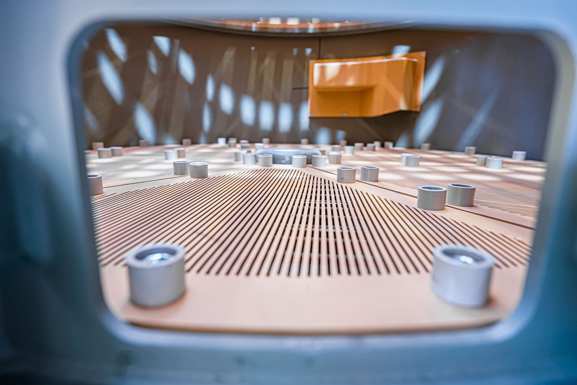
The material loaded into the feeder contains some fines delivered with the material as well as fines picked up by the bucket loader when it scoops material up from the storage piles. This requires a screen deck section with a collection bin below it to hold the fines. The holding bin had to be designed to store a reasonable amount of material so it does not have to be emptied often, but it also had to be located so that a forklift can easily and quickly exchange it.
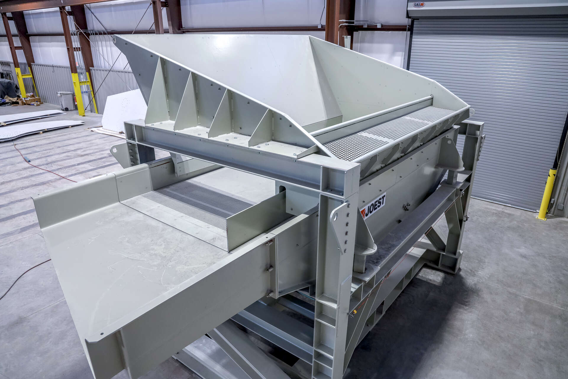
In addition to the scrap material, the feeder must also feed alloy material that ranges in size from 5mm to 300mm. The alloy material can be smaller than the openings in the screen section used to remove contamination fines, so the alloy material cannot pass over the open holes of the fines screen. Joest evaluated several previously proven ways to mechanically close the openings in the screen section when feeding the alloys. Due to the characteristics of the alloys, these methods were complicated, costly and could have difficulty repeatedly sealing the openings. While cost effective, replacing the perforated section with a solid plate when running alloys was not practicable because of the size and weight of the blanking plates and frequency of performing this operation.
The solution was to design the feeder pan with an additional, parallel solid pan that runs the length of the feeder and bypasses the fines screen section. The infeed hopper had to be designed to allow the alloy material to be easily loaded with a bucket loader into just the bypass portion of the feeder. As an added feature, the alloy loading area was equipped with a perforated cover on top to screen out any oversized alloy material, as well as any scrap material that may accidentally fall into this area.
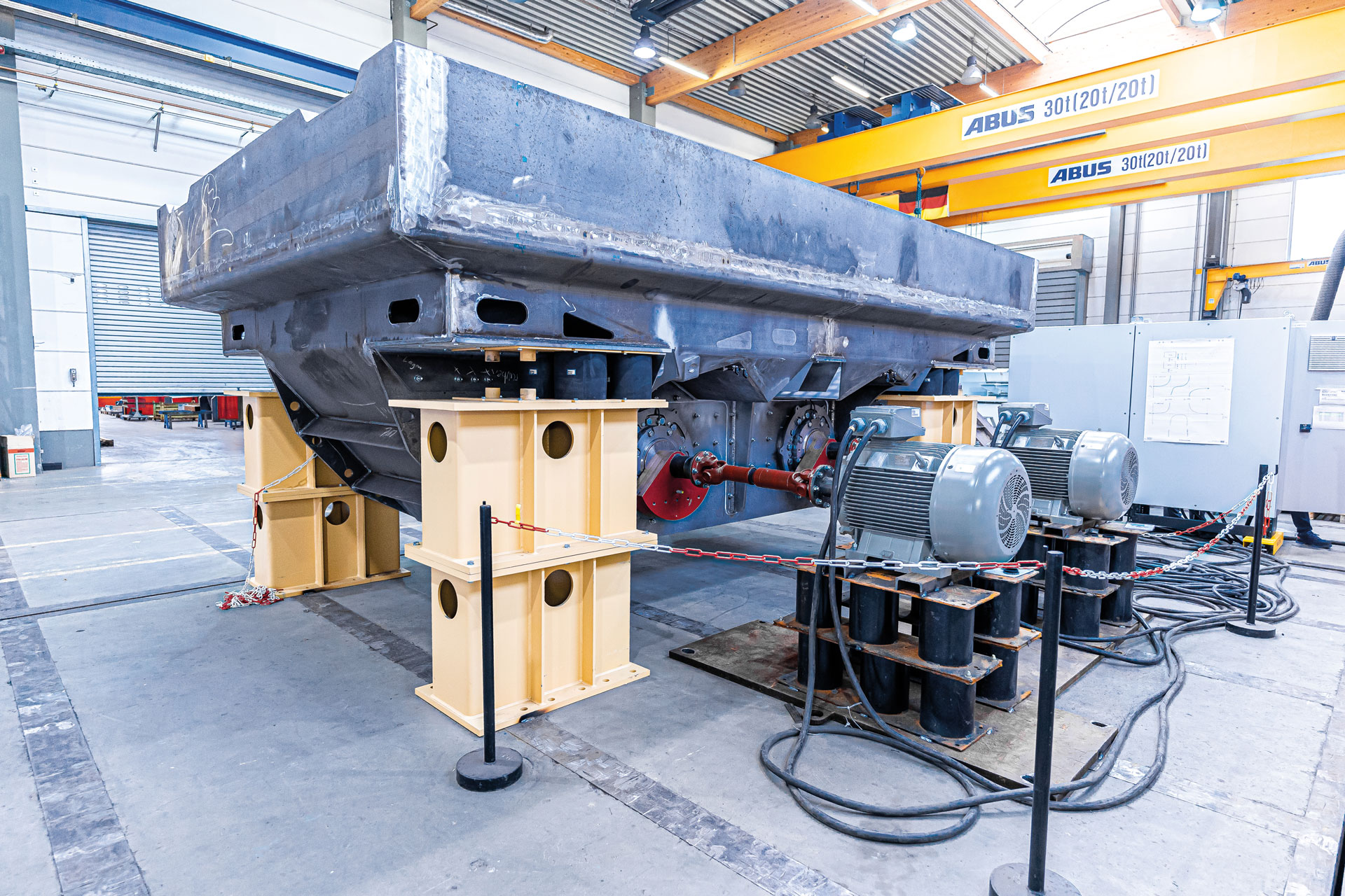
As a result of the asymmetric pan, this design had to accommodate off-centered loads on the drives, maintain adequate openings for loading the scrap and alloy materials, and achieve the desired throughputs. All this was accomplished while limiting the width of the feeder to be less than the width of the furnace.
You can find more information about our machines and processes here:
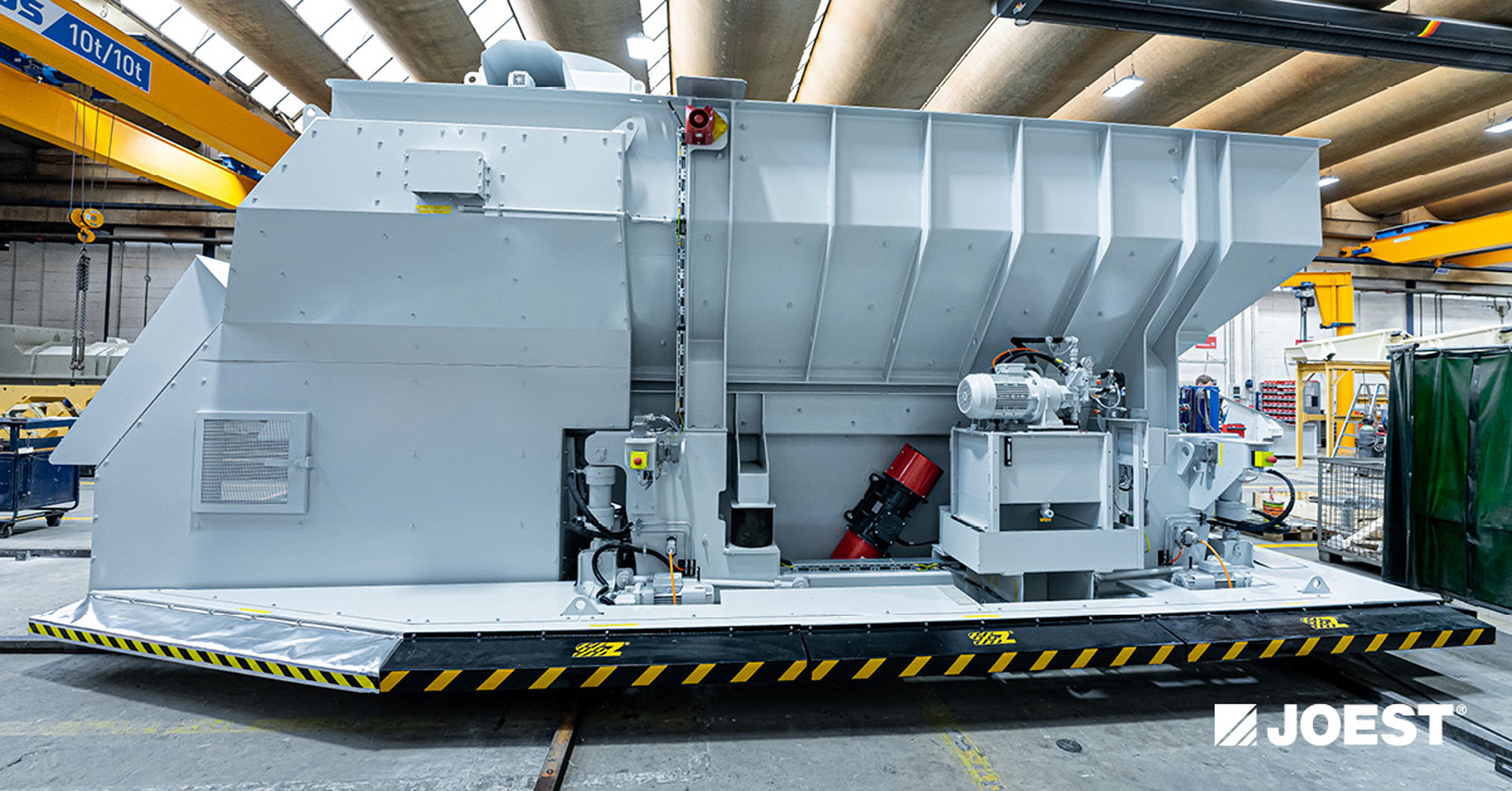
MANUAL MOVEMENT OF FEEDER
Traditional charge cars run automatically on a set of rails. Special bumpers with sensors ensure safe operation when personnel and obstructions are in the path of the car’s movement. Unfortunately, the cost of the automation portion of this solution was not within the customer’s budget. Also, the floor was too rough to reliably keep debris from getting into the rail bed and interfering with the cart’s wheels. Splattering metal from the furnace may also get on the rail bed. The resulting need and frequency of cleaning the rail bed was also a factor.
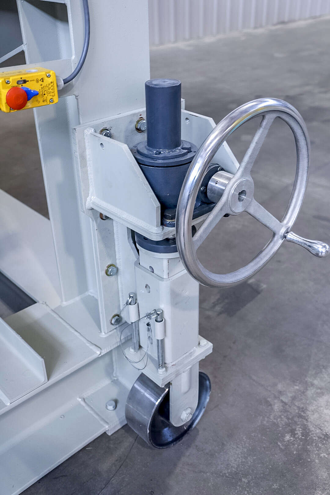
Manual, free-form movement of the feeder was chosen. Increasing the weight of the cart ensured the cart would not move when set on the ground, but the added weight now exceeded the lift capacity of the current forklifts.
The feeder frame was designed so it can be pushed by lifting one end with a forklift while the other end rolls on retractable wheels. The size and type of wheels were chosen to accommodate the rough floor. The handle and gear ratio of the wheel mechanism were chosen to make the extension and retraction of the wheels easy and ergonomic.
SIMPLE SECURING OF THE FEEDER
Traditional charge cars run automatically on a set of rails. Special bumpers with sensors ensure safe operation when personnel and obstructions are in the path of the car’s movement. Unfortunately, the cost of the automation portion of this solution was not within the customer’s budget. Also, the floor was too rough to reliably keep debris from getting into the rail bed and interfering with the cart’s wheels. Splattering metal from the furnace may also get on the rail bed. The resulting need and frequency of cleaning the rail bed was also a factor.
Manual, free-form movement of the feeder was chosen. Increasing the weight of the cart ensured the cart would not move when set on the ground, but the added weight now exceeded the lift capacity of the current forklifts.
The feeder frame was designed so it can be pushed by lifting one end with a forklift while the other end rolls on retractable wheels. The size and type of wheels were chosen to accommodate the rough floor. The handle and gear ratio of the wheel mechanism were chosen to make the extension and retraction of the wheels easy and ergonomic.
![]()
CONCLUSION
It took serval iterations during the concept engineering phase of the project to identify and pull all the solution features into one design. The customer was forthright with the different design requirements and an integral part of the brainstorming, evaluation and concept engineering phases.
There are several companies that can make a simple, standard feeders, but few who have the industry experience, engineering capability, and creative problem solving skills to make custom solutions to totally satisfy all the customer’s needs. This custom design work then feeds back into the process to make better standard solutions and continually help Joest to push the limits to meet the next, even greater challenge.